This post is long overdue, but here is a quick recap of my AC replacement.
About a year ago the window AC unit in the fermentation chamber went out when I was making batch +8. I’m pretty sure this is the reason that batch ended in bottle bombs. I wasn’t too disappointed in the AC failing because I felt that it was working more than it should. It appeared to let a lot of cool air out of the unit itself causing it to kick on more than I thought it should. So I decided I’d reuse the guts of a small cube fridge. In hindsight, I wish I had used a bit larger of a cooler as it appears that I can only hold a 35 degree temperature difference. This is sufficient for fermenting, but not good enough to get a good cold crash when the garage is in the 80s.
Taking apart the mini-fridge was pretty easy once I bought a pair of sheet metal scissors. From there it was pretty easy to mount the cooling tray and add the insulation. I certainly didn’t sand and paint as good as I did in the original build, but it works. Finally, I added a pc fan to continually blow across the cooling tray; without it I noticed that it would ice up when trying to cool. I’m seeing a bit more condensation that I expected and have a towel to catch things. I’m trying to limit the amount of times I open and close the fridge for now, but this is something I’ll have to keep an eye on. All in all, it works and I’m back to brewing!
Trying to start a project just as you become a dad isn’t the best plan, but I’ve finally completed my fermentation chamber after about 6 months. I’m already making a beer in it and so far it is working great. The ironic thing is that the temperature is about 70 degrees right now and the fermentation chamber doesn’t really have to do anything, but at least I’ve staying at a constant temperature.
First things first, here are pictures of the completed project (click an image for a larger view)
Supplies
I bought my things from four main places. The temperature controllers came from E-bay, the A/C unit was from craigslist, the 110VAC lights, switches and relays are from Allelectronics.com, and the rest of the material was from Home Depot. The box is made of 2x4s, 1/4 plywood, and 2 inch foam. I used foam glue to attach the plywood to the foam and 2″ screws to join all the 2x4s. To join the foam pieces together and cover holes I used Great Stuff. After I add up all the pieces I spent just a bit under $500. I bought a few tools, but was able to borrow most of the big tools from family and friends. The most surprising thing was how expensive outlets, outlet boxes, fuse holders, and the controller box were.
The Build
Overall the project came together pretty close to the plan. I can’t cut straight, follow my directions, or paint, but other than that I did pretty good. The borrowed tools really helped cutting relatively straight lines, not straight, but straight enough. When I built the controller box I had a few errors that needed correcting, but that was fine and not completely unexpected. I also didn’t like how my doors were going to seal so I added another foam border to help with that.
The control box almost was a disaster. I used a bremel to cut out the switches with no problem. The wiring went to plan. I did have a bit of difficult soldering the wires to the switch contact points, but eventually got it. the I used a few contact boards to provide a secure attach point for the external wires to the internal wires. At the very end I almost couldn’t get the lid to close. I had to move and twist the wires around and apply some pressure to finally seal things up. I had two mistakes during this build. First, my initial wiring for the relay looked really good, but upon testing I discovered that I did about 50% of the connections wrong and had to redo it all. Finally, once it was all sealed up I discovered that my compression did break a couple of contacts that I had to go in and fix. But in the end the controller works great and looks pretty good.
As an extra thing that I worked on while I couldn’t get down to the garage is that I converted two old cell phones into IP webcams, one to watch the control panel and the other inside the chamber to watch the fermenting process and to double check temperatures. To get my wifi signal to reach the garage I had to setup a wifi repeater. The two phones were android phones and I was able to use free apps to setup the webcams. I installed IP Webcam for the webcams, droid VNC server to get into the phone remotely along with Screen Widget to turn the screen off (if needed). Finally, I can watch the webcams with the built in webpages from IP Webcam and I also use IP CAM Controller to see things from my phone. I had planned for this which is why I have an outlet not controlled by the STC-1000s so that the internal cell phone could remain on all the time.
Here are several photos during the build (click an image for a larger view)
Looking Back
Now that I’ve build my project I think I’d do it a bit different next time.
I’d probably simplify all the cuts I have to do and make the outer plywood fit around the foam entirely then have the 2×4 brace around it. This would make the project cost just a bit more, but it would save so much time.
I’d make the doors fit flush with the outside edges rather than fit inside the openings to make the seals easier. I didn’t follow my original plan for the doors as I was worried they wouldn’t seal well.
I would make the A/C cutout a bit larger. This ould make it easier for the great stuff to get in the cracks. I didnt’ have much space and don’t really know how well I sealed this in. (I’m yet to do a dry ice test).
I was excited and cut the foam pieces first, but looking back I should have made the frame and then cut the foam to fit into it. I’m pretty sure my method is a rookie mistake, but I was excited to see the foam cut out.
Next Steps
I haven’t made the dividing section so that I can have two temperature zones inside. I have the controller and the wiring all done and all is left is to figure how I would do this. I’m thinking some type of relay to open and close a small opening and then a fan to circulate air. I also have to figure out how to make the section so that it can be moved around and then “expanded” to give it a tighte fit. I’ll have to think about this for a while, until then…
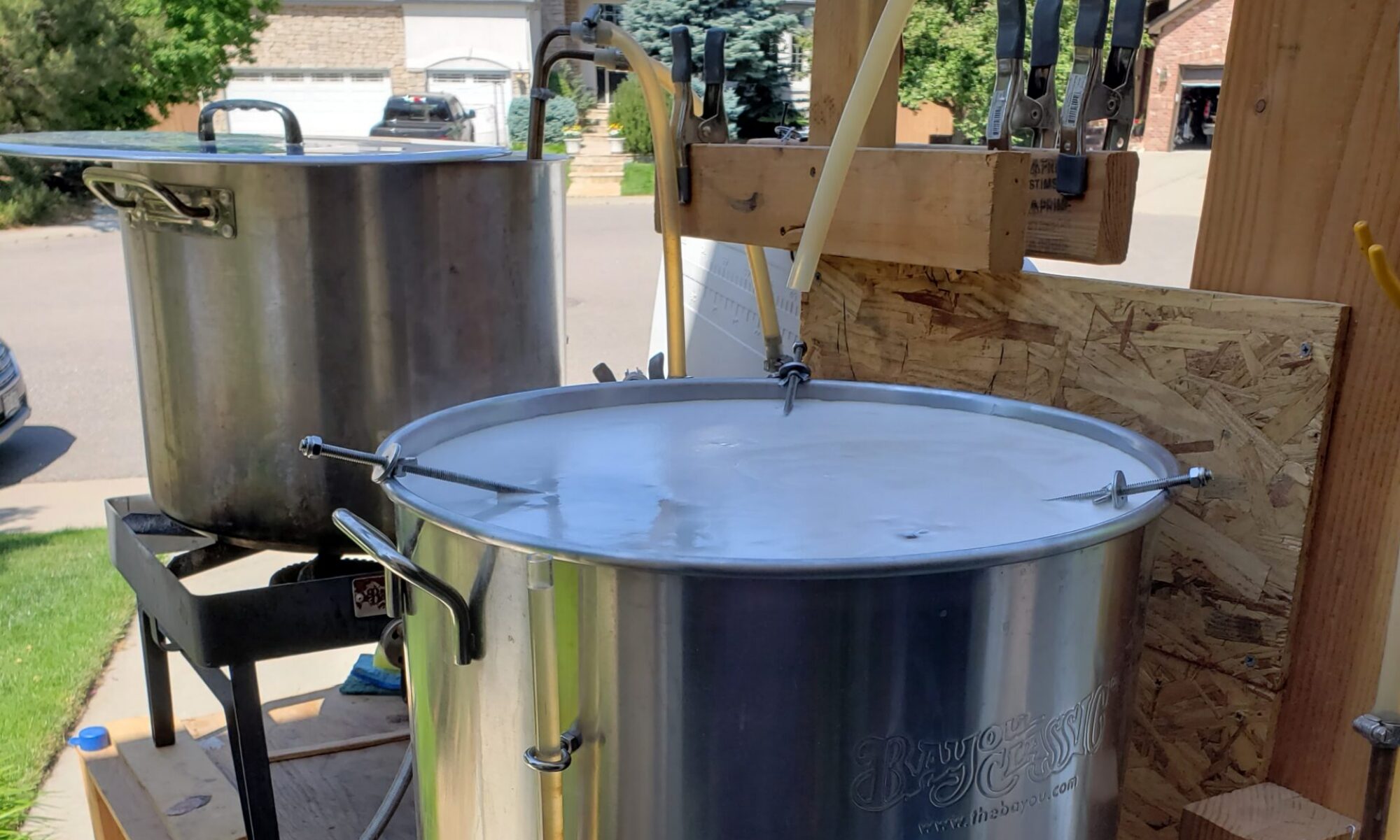
After my last batch of beer, Baby-T Double Trouble Belgium Dubble, came up short on the alcohol content I’ve decided that my problem is due to my fermentation temperatures…and possibly my aeration. I was also having a hard time using my wort chiller since the hose water that I’ve circulated through it wasn’t too cold. So I’m stepping it up a notch.
I got a drill off of Craiglist for about $20 and a drill water pump from Home Depot. Next time I chill the wort I’ll be circulating iced water from a cooler through the chiller which should bring the temps down right away. I also bought a large drill-attached paint mixer to help aerate the wort after it is chilled. One thing I’m slightly hesitant on is that while I plan to sanitize the mixer, I don’t know if I’ll run into any problems since it isn’t a food grade mixer. I guess I’ll learn soon enough.
Now to the main issue, temperature control. For all my batches to date I’ve simply left the beer to ferment in the back of the garage. The temperature usually stays around 60 degrees, but on really hot days it will rise to 70 and on consecutive cold days it will drop to low 50s. For my last batch I started fermenting right as a cold spell hit which I’m pretty sure caused the yeast to not ferment all the sugars. After a lot of reading the only way I’m going to get around the problem is to get some temperature regulation through a fermentation chamber.
I did a lot of reading in the http://www.homebrewtalk.com forums to get ideas of how to go about building a fermentation chamber. I think there are basically three types of chambers, those that use ice, those that use a fridge components, and those that use air conditioners. The ice ones are simple (1,), but if you ask me annoying to maintain. The fridge styles have many variations. Some work as is, some take some cutting of the interior to make room for a carboy (1,2,), some look to extend the fridges dimensions with some type of add on (1,), and others strip out the cooling component and then use a custom box (1,). For the AC styles they are pretty much the same, take an AC unit and build a custom box (examples below).
Our garage is already packed with stuff, so the custom box idea was the most attractive to me. The next part was to decide fridge or AC which is the single most expensive part. I simply trolled Craiglist for a while until I found something cheap. For me it ended up being a $30 Haier 5000BTU AC unit (HWF05XCK-1) which I learned was purchased from Target the year prior when we were having a huge summer heat wave and the person selling it was moving to Saudi Arabia. I joked with the person that they probably should have taken the unit with them, but assured them that I’d put it to good use. Anyways, just as noted in the Racer X design to override the temperature cutoff on the AC unit a simple loosening of the screw behind the temperature knob will do the trick.
AC Unit with my measurements (click the picture for a larger view)
[singlepic id=27 w=320 h=240 float=none]
The screw is here (hard to see) [singlepic id=18 w=320 h=240 float=none]
This is the other side, do not mess with this screw [singlepic id=16 w=320 h=240 float=none]
With the screw loosening I rigged up a quick test to see that I did things just right
[singlepic id=19 w=320 h=240 float=none]
The temperature is down to 36 degrees F! [singlepic id=20 w=320 h=240 float=none]
With the AC unit and the idea to make a custom box, I needed to sort out the temperature controller. I very very long forum about an aquarium temperature controller that can be bought on ebay seemed like the ticket for me. This controller usually can be bought for $15-$20 and I got my first one for $15.50 and the second for $18.25 (I’ll explain later…which if I knew how to do ebay better should have been $17, but I’ve wasted $1.25 on worse before). Here is a quick look at one with my measurements marked up on it: [singlepic id=28 w=320 h=240 float=none]
Now off to design the chamber. My design was strongly influenced one the 2 Tier, 2 Zone fermentation chamber (Racer X). It is a really nice build and as it turns out I ended up with the exact same AC unit as his (even though they are listed as different brands). This chamber is really nice as it allows for one cooling unit and two temperature controllers to create the two zones. There are a few others with similar ideas that I looked at too (1, 2, )
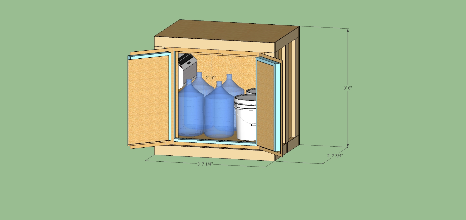
I decided that while I really like the 2 zone idea I don’t need that right now, but that I’d make my design with a future expansion in mind. I wanted to make sure that this could hold a keg plus kegging gear, 3 soda kegs plus gear, 4 carboys, or 4 5G buckets, or 2 buckets and all of my other brewing gear so that I’m not scattered all over the garage. With this in mind I settled on an interior dimension of 34″ x 36″ x 24.5″ (height, width, depth when looking at the front).
Additionally, here are a few design notes that I took from all my forum reading
Use the best (i.e. highest R-rated) rigid foam. A look at Home Depot says there is a 2″ foam with an R-10 value that is moisture resistant
Seal all the edges to avoid air leaks
A 2×4 is not 2″ by 4″. It is really 1.5″ x 3.5″
On the interior paint the inside with a mildew resistant paint and caulk the edges.
I want easy access to the interior. No top doors so that I can leave things on the top.
I messed around for a bit trying to figure out how I would go about designing this. When I did my bar a few (many) years back, which I’ll post about some other time, I did it all in excel where each cell represented 0.25″. that worked out well, because a quarter inch was the smallest thickness of wood that I used. For this design I plan to use 1/8″ plywood and excel just won’t work as there are too many cells needed. I ended up doing the design the simple way, engineering paper, a ruler, and a pencil. For the most part I had each square represent 2″. The 1/8″ is hard to draw clearly, but I made it work. I won’t go into all the effort spent making the design, but below are the drawing for the chamber. As in the Racer X design, the doors are the hardest part. I decided to have two doors that swing open from the sides. If you look carefully at the design, I’ve staggered the plywood and foam cutting one inch from the sides, the top, and between the doors. With this staggered approach the doors actually don’t come together in the middle, but I have a door cover that makes it appear as if it does. I need to sort out how to add the weather stripping, but for now I’m planning on just slicing a bit of foam away from the edges for it. The other thing that I know I have left off is the hole for the AC unit. I’m planning to simply cut as needed and figure the support required to keep it at the proper angle (note the AC unit isn’t supposed to be level.).
Once I had the design drafted I determined how much wood and foam I’d need. I was able to get it down to 13 2x4s, 2 foam sheets, and 3 plywood sheets.
[singlepic id=26 w=320 h=240 float=none]
The next thing I needed to sort out was how I was going to wire the chamber up. The temperature controller forum had a lot of good ideas. I decided that I’d have one outlet for the hot, one for the cold, and two for either hot or cold. I also wanted to be able to turn the outlets on and off without unplugging them so I needed a switch. I added some indicator lights. I added another switch for another outlet that I can keep on the outside of the chamber. I’m going to wire up the second temperature controller to just be a simple thermometer since the temperature probe on the beer will be slightly different due to the exothermic reaction of the yeast fermenting beer. I plan to have this whole circuit plugged into a 20A circuit, but the temp probes are only rated for 10A so I’ve added a 10A fuse to each circuit. 10A will be plenty as the AC unit is only ~4A and I don’t intend to pull a full 20A at once. As I mentioned above I got the temperature controllers off of ebay. I found a really good deal on switches, relays and indicators from allelectronics.com and now just need to get the outlets, wire, and boxes.
[singlepic id=21 w=320 h=240 float=none]
So that is all the planning which I did before my birthday. In hopes of getting some home depot gift cards I’ve waited a while to actually get going on this. In my free time which is very limited now that we have baby Chase on our hands I modeled the design in Sketchup. This took me a bit of learning to be effective at this, but after a short while I got the hang of it and was able to put together the plans. Good thing too as I learned a few things that caused me to make some adjustments in the design.
Click the link to see the animated sketchup of the design