Fermentation Chamber – Completed

Trying to start a project just as you become a dad isn’t the best plan, but I’ve finally completed my fermentation chamber after about 6 months.  I’m already making a beer in it and so far it is working great.  The ironic thing is that the temperature is about 70 degrees right now and the fermentation chamber doesn’t really have to do anything, but at least I’ve staying at a constant temperature.

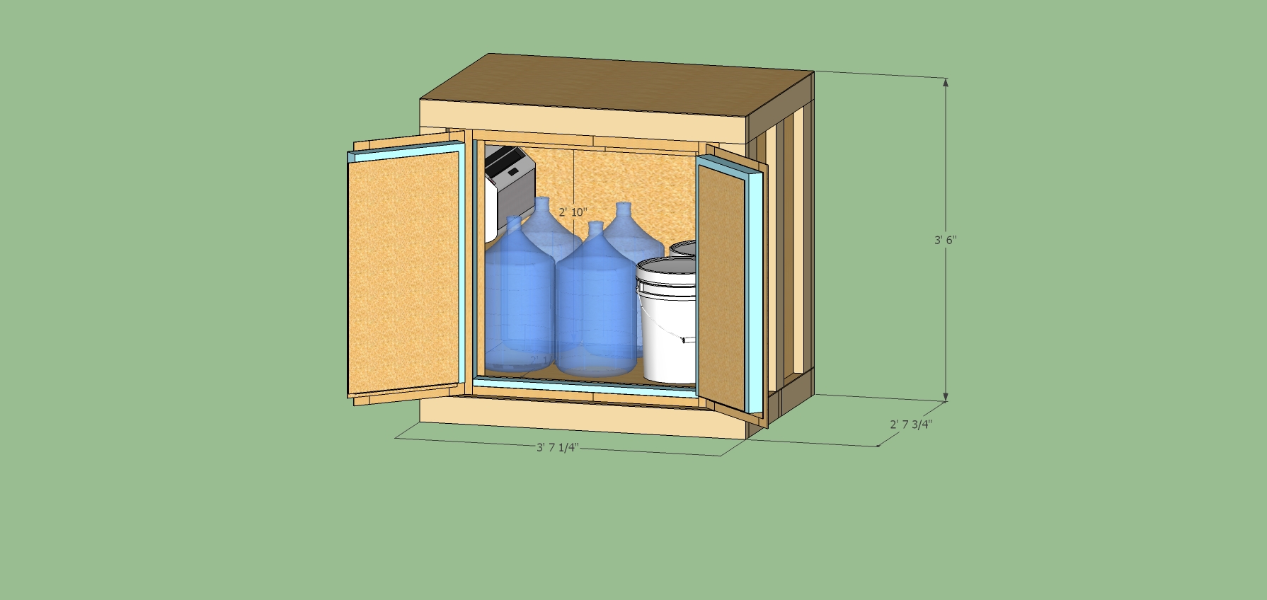
First things first, here are pictures of the completed project  (click an image for a larger view)


Supplies

I bought my things from four main places.  The temperature controllers came from E-bay, the A/C unit was from craigslist, the 110VAC lights, switches and relays are from Allelectronics.com, and the rest of the material was from Home Depot.  The box is made of 2x4s, 1/4 plywood, and 2 inch foam.  I used foam glue to attach the plywood to the foam and 2″ screws to join all the 2x4s.  To join the foam pieces together and cover holes I used Great Stuff.  After I add up all the pieces I spent just a bit under $500.  I bought a few tools, but was able to borrow most of the big tools from family and friends.  The most surprising thing was how expensive outlets, outlet boxes, fuse holders, and  the controller box were.

The Build

Overall the project came together pretty close to the plan.  I can’t cut straight, follow my directions, or paint, but other than that I did pretty good.  The borrowed tools really helped cutting relatively straight lines, not straight, but straight enough.  When I built the controller box I had a few errors that needed correcting, but that was fine and not completely unexpected.  I also didn’t like how my doors were going to seal so I added another foam border to help with that.

The control box almost was a disaster.  I used a bremel to cut out the switches with no problem.  The wiring went to plan.  I did have a bit of difficult soldering the wires to the switch contact points, but eventually got it.  the I used a few contact boards to provide a secure attach point for the external wires to the internal wires.  At the very end I almost couldn’t get the lid to close.  I had to move and twist the wires around and apply some pressure to finally seal things up.  I had two mistakes during this build.  First, my initial wiring for the relay looked really good, but upon testing I discovered that I did about 50% of the connections wrong and had to redo it all.  Finally, once it was all sealed up I discovered that my compression did break a couple of contacts that I had to go in and fix.  But in the end the controller works great and looks pretty good.

As an extra thing that I worked on while I couldn’t get down to the garage is that I converted two old cell phones into IP webcams, one to watch the control panel and the other inside the chamber to watch the fermenting process and to double check temperatures.  To get my wifi signal to reach the garage I had to setup a wifi repeater.  The two phones were android phones and I was able to use free apps to setup the webcams.  I installed IP Webcam for the webcams, droid VNC server to get into the phone remotely along with Screen Widget to turn the screen off (if needed).  Finally, I can watch the webcams with the built in webpages from IP Webcam and I also use IP CAM Controller to see things from my phone.  I had planned for this which is why I have an outlet not controlled by the STC-1000s so that the internal cell phone could remain on all the time.

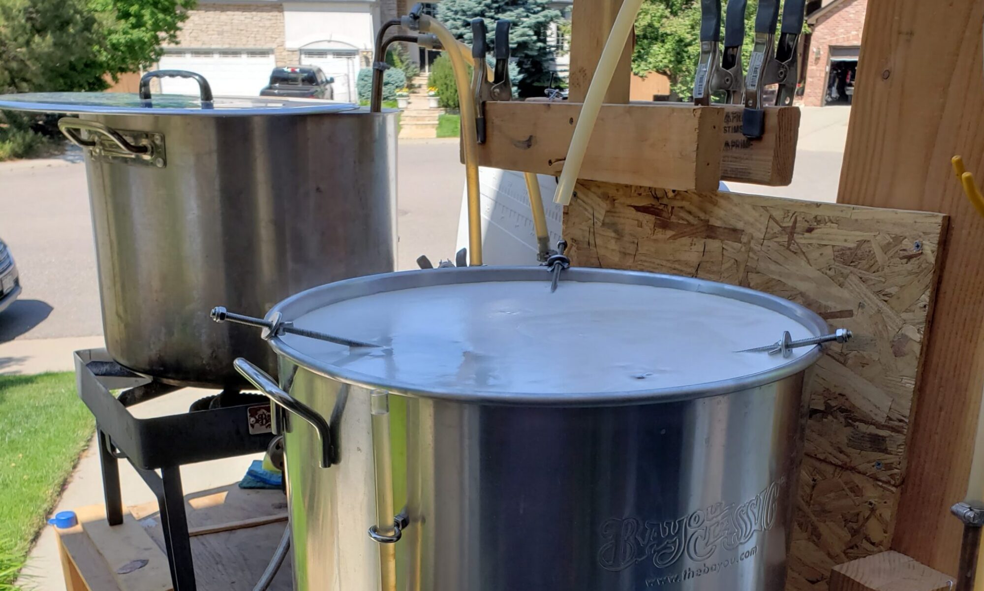
Here are several photos during the build  (click an image for a larger view)

Looking Back

Now that I’ve build my project I think I’d do it a bit different next time.

  1. I’d probably simplify all the cuts I have to do and make the outer plywood fit around the foam entirely then have the 2×4 brace around it.  This would make the project cost just a bit more, but it would save so much time.
  2. I’d make the doors fit flush with the outside edges rather than fit inside the openings to make the seals easier.  I didn’t follow my original plan for the doors as I was worried they wouldn’t seal well.
  3. I would make the A/C cutout a bit larger.  This ould make it easier for the great stuff to get in the cracks.  I didnt’ have much space and don’t really know how well I sealed this in. (I’m yet to do a dry ice test).
  4. I was excited and cut the foam pieces first, but looking back I should have made the frame and then cut the foam to fit into it.  I’m pretty sure my method is a rookie mistake, but I was excited to see the foam cut out.

 Next Steps

I haven’t made the dividing section so that I can have two temperature zones inside.   I have the controller and the wiring all done and all is left is to figure how I would do this.  I’m thinking some type of relay to open and close a small opening and then a fan to circulate air.  I also have to figure out how to make the section so that it can be moved around and then “expanded” to give it a tighte fit.  I’ll have to think about this for a while, until then…

Repeater bridge is now setup

I’m happy to say that I just got a repeater bridge setup using DD-wrt on both routers.  In the garage and in one bedroom the wireless signal from the main router doesn’t come in very well (or not at all).  this is particularly troubling since I plan to use some old phones as IP webcams to watch my beer ferment whenever I finish my fermentation chamber.

I read a lot of sites and watched several YouTube videos and failed many times.  Though I’m sure most sites were right I think the problem that I had was the encryption between the main router and the repeater router. Many blogs recommended getting the connection to work without without and then one that works setup the encryption.

I did a similar thing as many sites but with a one twist. Rather that have the repeater router connect to the main router over the real wireless lan (wl0), I setup a virtual lan on the main router. This allowed for a few nice things. First, I spent a really long time trying to get it setup directly to the wl0, jumping straight into an AES+TKIP link, and could never get it to work.  Secondly, once I went this route  I could mess with the setup without impacting the normal network with a few exceptions. This also allowed me to do the setup without turning the normal wireless into an unencrypted link.  Also, now my bridge link is hidden so I should really have any thing else using this link.

When I set this up I followed this YouTube video pretty extensively which for the changes of using a virtual lan on my main router the instructions are good.  When I got things connected I started with the AP_Bridge being visible and no encryption.  I then added the encryption and things worked.  I suppose I could have tried AES+TKIP, but I was happy with what I had working given that I spent a really long time prior to this.  Once that worked I hid the AP_Bridge.  To test things out I reset the Repeater_Bridge and it was able to connect just fine.    A quick check in the garage shows a strong signal from the repeater bridge and I should be set to go now.
Continue reading “Repeater bridge is now setup”

Jeep 730N RHR Nav Display Upgrade

Well it turns out Jeep has done a pretty bad job of maintaining the navigation unit software which has been buggy at best.  In our case it is the 730N RHR unit on the Jeep Grand Cherokee  After a lot of searching, mostly in the Jeep Garage website,  I was able to find a person, *sox*,  that hosts the files to upgrade the unit as described in this forum post.

Download the Files

Below is the link, username, and password to get the files.

www.mydrive.ch
username: mygig@soxag
password: gasolio

You will be downloading two files.  The software and the gracenotes ISOs.

As many posts point out version 2.169 is really buggy, was never released, and should not be used.  When I wrote this post 2.136 was the latest version to download.  Though I wonder if a new version is on the way since I saw a person post that they have 2.137.  Below is the path to the ISO file

 Home  MyGIG Software Update  Software – Gracenotes update  RHR-RHW-RHP 2011+ 

Next is the gracenotes.  At the time of this post 4118 was the latest version.  Below is the gracenotes file

 Home  MyGIG Software Update  Software – Gracenotes update  Gracenotes update  Gracenotes RHR-RHW-RHP 2011+ 

Once you have the files you can go about installing the files either of two ways: CD or USB

CD Method

If using the CD method many people, including myself, have had success using the free ImgBurn program.  Simply select the ISO file to burn to the CD and done.  Note: only one ISO per CD.

  1. Turn Car On to at least Accy mode. No need to start the ignition.
  2. Press power on 730n
  3. Load CD into CD Drive
  4. Close Door
  5. It can take a minute for the cd to be recognized.  If it isn’t eject the cd and start over on step 3.
  6. See the installation below

USB Method

I haven’t given this option a try but several posts have reported success. You’ll need a 4GB USB drive to do this.

  1. Turn Car On  to at least Accy mode. No need to start the ignition.
  2. Insert USB drive into USB port on radio.
  3. Press power on radio to turn radio off.
  4. Wait 5 to 10 Seconds and power Radio back on.
  5. It can take a minute for the USB drive to be recognized.  If it isn’t start over.

 Installation

Once it recognized the CD or USB drive you should be prompted to “Proceed with Update”  It will show you the current version and the version it will upgrade to.  Assuming this is what you want press Yes.  The installation took a while, but once it was done you can confirm the upgrade was successful in the System information.


[singlepic id=37 w=320 h=240 float=none]

[singlepic id=38 w=320 h=240 float=none]

[singlepic id=36 w=320 h=240 float=none]

[singlepic id=41 w=320 h=240 float=none]

 Parting thoughts

Hope this helps someone.  Turns out our hard drive failed in the unit and Jeep had to replace it.  The techs were suprised to see that my unit was upgraded to the latest version which goes to show how poor Jeep is at keeping the customers up to date.  Since the new hard drive was replaced and with the 2.136 version has been installed the nav unit has been much more stable.

SD Card Scare

Just survived a scare, the SD Card in my phone became unrecognized and I was worried that I lost all my camera photos. So my phone died when I was at work so the phone shutdown. When I got in my car I left it on the car charger for just a little while and then tried to turn it on. Apparently I didn’t wait long enough because just as the Android OS booted up the phone died again. Side note, a car charger doesn’t charge a phone faster than it can drain it with the screen and all the antennas on. Later when I got home and charged my phone long enough the SD Card came up and unrecognizable and Android asked if I wanted to format it.

After a few searches and several unsuccessful suggestions I remembered that I have a program, MiniTool Partition Wizard, that might do the trick.  It has an option to scan and repair a partition.  So I ran the scan with detect and repair option selected and it discovered that it was formatted for FAT32 and that the “/” link was bad.  It did some repairs and the presto my SD card was recognizable by Windows 7.  I plugged it back into my phone and life is good again.  I think I’m going to make sure a backup is done tonight…

Dilbert

Fermentation Chamber – The Planning

After my last batch of beer, Baby-T Double Trouble Belgium Dubble, came up short on the alcohol content I’ve decided that my problem is due to my fermentation temperatures…and possibly my aeration.  I was also having a hard time using my wort chiller since the hose water that I’ve circulated through it wasn’t too cold.  So I’m stepping it up a notch.

I got a drill off of Craiglist for about $20 and a drill water pump from Home Depot.  Next time I chill the wort I’ll be circulating iced water from a cooler through the chiller which should bring the temps down right away.  I also bought a large drill-attached paint mixer to help aerate the wort after it is chilled.  One thing I’m slightly hesitant on is that while I plan to sanitize the mixer, I don’t know if I’ll run into any problems since it isn’t a food grade mixer. I guess I’ll learn soon enough.

Now to the main issue, temperature control.  For all my batches to date I’ve simply left the beer to ferment in the back of the garage.  The temperature usually stays around 60 degrees, but on really hot days it will rise to 70 and on consecutive cold days it will drop to low 50s.  For my last batch I started fermenting right as a cold spell hit which I’m pretty sure caused the yeast to not ferment all the sugars.  After a lot of reading the only way I’m going to get around the problem is to get some temperature regulation through a fermentation chamber.

I did a lot of reading in the http://www.homebrewtalk.com forums to get ideas of how to go about building a fermentation chamber.  I think there are basically three types of chambers, those that use ice, those that use a fridge components, and those that use air conditioners.  The ice ones are simple (1,), but if you ask me annoying to maintain. The fridge styles have many variations.  Some work as is, some take some cutting of the interior to make room for a carboy (1,2,), some look to extend the fridges dimensions with some type of add on (1,), and others strip out the cooling component and then use a custom box (1,).  For the AC styles they are pretty much the same, take an AC unit and build a custom box (examples below).

Our garage is already packed with stuff, so the custom box idea was the most attractive to me.  The next part was to decide fridge or AC which is the single most expensive part.  I simply trolled Craiglist for a while until I found something cheap.  For me it ended up being a $30 Haier 5000BTU AC unit (HWF05XCK-1) which I learned was purchased from Target the year prior when we were having a huge summer heat wave and the person selling it was moving to Saudi Arabia.  I joked with the person that they probably should have taken the unit with them, but assured them that I’d put it to good use. Anyways, just as noted in the Racer X design to override the temperature cutoff on the AC unit a simple loosening of the screw behind the temperature knob will do the trick.

AC Unit with my measurements (click the picture for a larger view)
[singlepic id=27 w=320 h=240 float=none]

The screw is here (hard to see) [singlepic id=18 w=320 h=240 float=none]
This is the other side, do not mess with this screw [singlepic id=16 w=320 h=240 float=none]

With the screw loosening I rigged up a quick test to see that I did things just right
[singlepic id=19 w=320 h=240 float=none]
The temperature is down to 36 degrees F! [singlepic id=20 w=320 h=240 float=none]

With the AC unit and the idea to make a custom box, I needed to sort out the temperature controller.  I very very long forum about an aquarium temperature controller that can be bought on ebay seemed like the ticket for me.  This controller usually can be bought for $15-$20 and I got my first one for $15.50 and the second for $18.25 (I’ll explain later…which if I knew how to do ebay better should have been $17, but I’ve wasted $1.25 on worse before). Here is a quick look at one with my measurements marked up on it: [singlepic id=28 w=320 h=240 float=none]

Now off to design the chamber.  My design was strongly influenced one the 2 Tier, 2 Zone fermentation chamber (Racer X).  It is a really nice build and as it turns out I ended up with the exact same AC unit as his (even though they are listed as different brands).  This chamber is really nice as it allows for one cooling unit and two temperature controllers to create the two zones.  There are a few others with similar ideas that I looked at too (1, 2, )

I decided that while I really like the 2 zone idea I don’t need that right now, but that I’d make my design with a future expansion in mind.  I wanted to make sure that this could hold a keg plus kegging gear, 3 soda kegs plus gear, 4 carboys, or 4 5G buckets, or 2 buckets and all of my other brewing gear so that I’m not scattered all over the garage.  With this in mind I settled on an interior dimension of 34″ x 36″ x 24.5″ (height, width, depth when looking at the front).

Additionally, here are a few design notes that I took from all my forum reading

  • Use the best (i.e. highest R-rated) rigid foam.  A look at Home Depot says there is a 2″ foam with an R-10 value that is moisture resistant
  • Seal all the edges to avoid air leaks
  • A 2×4 is not 2″ by 4″.  It is really 1.5″ x 3.5″
  • On the interior paint the inside with a mildew resistant paint and caulk the edges.
  • I want easy access to the interior.  No top doors so that I can leave things on the top.
  • 20A requires 12 guage wire.  10A requires 18 gauge.

I messed around for a bit trying to figure out how I would go about designing this.  When I did my bar a few (many) years back, which I’ll post about some other time, I did it all in excel where each cell represented 0.25″.  that worked out well, because a quarter inch was the smallest thickness of wood that I used.  For this design I plan to use 1/8″ plywood and excel just won’t work as there are too many cells needed.   I ended up doing the design the simple way, engineering paper, a ruler, and a pencil.  For the most part I had each square represent 2″. The 1/8″ is hard to draw clearly, but I made it work.  I won’t go into all the effort spent making the design, but below are the drawing for the chamber.  As in the Racer X design, the doors are the hardest part. I decided to have two doors that swing open from the sides. If you look carefully at the design, I’ve staggered the plywood and foam cutting one inch from the sides, the top, and between the doors. With this staggered approach the doors actually don’t come together in the middle, but I have a door cover that makes it appear as if it does. I need to sort out how to add the weather stripping, but for now I’m planning on just slicing a bit of foam away from the edges for it. The other thing that I know I have left off is the hole for the AC unit.  I’m planning to simply cut as needed and figure the support required to keep it at the proper angle (note the AC unit isn’t supposed to be level.).

[singlepic id=21 w=320 h=240 float=none]
[singlepic id=23 w=320 h=240 float=none]
[singlepic id=24 w=320 h=240 float=none]
[singlepic id=25 w=320 h=240 float=none]

Once I had the design drafted I determined how much wood and foam I’d need. I was able to get it down to 13 2x4s, 2 foam sheets, and 3 plywood sheets.
[singlepic id=26 w=320 h=240 float=none]

The next thing I needed to sort out was how I was going to wire the chamber up. The temperature controller forum had a lot of good ideas. I decided that I’d have one outlet for the hot, one for the cold, and two for either hot or cold. I also wanted to be able to turn the outlets on and off without unplugging them so I needed a switch. I added some indicator lights. I added another switch for another outlet that I can keep on the outside of the chamber. I’m going to wire up the second temperature controller to just be a simple thermometer since the temperature probe on the beer will be slightly different due to the exothermic reaction of the yeast fermenting beer. I plan to have this whole circuit plugged into a 20A circuit, but the temp probes are only rated for 10A so I’ve added a 10A fuse to each circuit. 10A will be plenty as the AC unit is only ~4A and I don’t intend to pull a full 20A at once. As I mentioned above I got the temperature controllers off of ebay. I found a really good deal on switches, relays and indicators from allelectronics.com and now just need to get the outlets, wire, and boxes.
[singlepic id=21 w=320 h=240 float=none]

So that is all the planning which I did before my birthday. In hopes of getting some home depot gift cards I’ve waited a while to actually get going on this. In my free time which is very limited now that we have baby Chase on our hands I modeled the design in Sketchup. This took me a bit of learning to be effective at this, but after a short while I got the hang of it and was able to put together the plans. Good thing too as I learned a few things that caused me to make some adjustments in the design.

Click the link to see the animated sketchup of the design
single-ferm-chamber-doors-open

Here are a few other views of the model

Doors closed [singlepic id=29 w=320 h=240 float=none]

Doors open with no objects [singlepic id=32 w=320 h=240 float=none]

with the future expansion [singlepic id=31 w=320 h=240 float=none]


In case anybody is interested here is the Single Ferm Chamber Sketchup File.

Well that is all for now and I’ll share the final product when it is done.

Dilbert

Soon to be Pro-Am Photographer

Lisa and I decided that we wanted to have a good camera to take a lot of baby Chase photos. Our little compact Lumix DMC-ZS3 just won’t cut it, but still really good camera to have. Also, I discovered that I had about $450 dollars worth of Boeing Pride points that I could convert to Best Buy gift cards. With that bit or money I make the knee jerk decision that we could afford a nice camera.

We figured that if we got a nice DLSR camera that we would get really good photos, but wouldn’t likely lug it around too often to get many of the in-the-moment photos. So I shopped around the latest removable lens / mirrorless cameras. After a few weeks of internet searching and store browsing we (or more accurately put, I) decided to get the Sony NEX-6 camera.


Fortunately, for us Best Buy was having a sale on cameras and lenses. They had a Sony NEX-6 kit that comes with camera and the normal lens, 16-50mm F3.5-5.6 E-mount Lens (SELP1650), and also a 55-210mm f/4.5-6.3 lens (SEL55210). Of course this was a good chunk of money more expensive, but with the gift cards I was feeling good about this.

with the SELP1650 lens
with the SEL55210 lens

I also splurged picked up a few accessories. I bought a nice little camera bag (Manfrotto Stile Solo II) that fits the camera, extra lens, the charger and wires great. The bag doesn’t have enough room for the light shade, but I’m okay with that.

I grabbed two rocketfish UV lens caps at Best Buy. They are ~$10 each and from the reviews I’ve read they don’t do too much, but are a great way to protect the real lens. Finally, Fry’s was having a great sale on Class-10 32GB SDHC memory cards and picked one up.

With all that I’m now set to be a premier pro-am photographer, though I don’t know what I’m doing. I’ve been done a bit or reading on how to use the camera, but mostly I’ve been reading on what all the sensor readings mean and how to take good photos. I know have a ton of photos of our candlesticks, Lisa’s last day flowers, and much to Lisa’s disapproval, her on the couch doing shutterfly stuff.

Well lets hope I learn quickly as baby Chase is due in less than 2 weeks!

New phone, Samsung Note 2, and already rooted

I just got a new phone.  After working really hard on my Evo shift I just couldn’t take the slowness anymore.  So I upgraded to a huge phone, the Samsung Note 2 on Sprint.  I’m still not too sure this is the phone for me as I’m worried about the size of it.  I almost bought the phone from Best Buy, but they were out of the titanium version and would have to mail it in.  So I decided to get it through Costco.  From Costco they had it as the same price, but covered the $36 upgrade fee and gave an additional car charger, case, and screen protector.  The phone was also mailed and it took about a week for it to come in.  Once I got the phone I charged the battery to full then went to work transferring phones over.

Samsung Note 2

Prepare for Transfer

In order to do an easy transfer from my old phone I did a Titanium backup of my apps. More specifically:

  1. Go into the Titanium Backup * root app
  2. Select Menu -> Batch actions ->Backup all user apps + system data

This should backup all the SMS messages too, but just in case it didn’t work is used SMS Backup & Restore

Rooting

I have the root version and really want to keep root on my phone.  Though at this time I have no desire to flash any ROMs or add a different recovery, but still want to get the OTA updates from Sprint/Samsung.  So I followed the directions posted on the XDA forums.  At the time of writing this post the VPALJC was the most current ROM.  I’ve copied the steps I followed, pretty much exactly as listed on the forum, so that I can recall what I did in the past.  I suggest reading the forum as it has a better chance of being kept up to date, whereas this post will be a simple moment in time.

Steps I followed to root and still maintain OTA updates.

  1. From your computer do the following
    1. Download Odin
    2. Unzip Odin
    3. Download the SPH-L900 (Samsung note 2) drivers from the Samsung’s site. Click on the Manuals & Downloads tab at the bottom and then on Software for the latest driver.
    4. Move the driver exe to the ODIN folder
    5. Download the mrRobinson‘s version of the firmware, VPALJC, from root66_SPR_L900VPALJC.7z
    6. Unzip the file and place into the ODIN folder
  2. From the phone
    1. Put the phone into download mode.
      1. Turn it off
      2. Then hold vol. down + home + power
      3. Choose accept to go into download mode
  3. From the computer
    1. Start the ODIN program
    2. Then in the PDA field and select the firmware file, root66_SPR_L900VPALJ1.tar.md5
    3. Leave Auto Reboot and F. Reset Time checked.
    4. Click start and wait for it to download the files to the phone, below is the message log I saw
    Enter CS for MD5..
    Check MD5.. Do not unplug the cable..
    Please wait..
    root66_SPR_L900VPALJC.tar.md5 is valid.
    Checking MD5 finished Sucessfully..
    Leave CS..All threads completed. (succeed 0 / failed 0)
    Added!!
    ID:0/003> Odin v.3 engine (ID:3)..
    File analysis..
    SetupConnection..
    Initialzation..
    Get PIT for mapping..
    Firmware update start..
    boot.img
    NAND Write Start!!
    cache.img
    hidden.img
    modem.bin
    param.bin
    recovery.img
    sboot.bin
    system.img
    tombstones.img
    tz.img
    RQT_CLOSE !!
    RES OK !!
    Removed!!
    Remain Port ....  0
    All threads completed. (succeed 1 / failed 0)
  4. When done let phone reboot and the phone is rooted
  5. I haven’t used or tested this yet to retain root privileges through an OTA update
    1. ,Get OTA Rootkeeper from the Google Play store on your phone
    2. Open OTA Rootkeeper and click “Protect Root”
    3. Then after you receive a notification for an OTA update you should go into OTA Rootkeeper and click something to re-enable root.
      1. Since I haven’t had to use this yet I don’t know what I will have to click nor do I know that this will work as the notes in the app say “Useless with: Samsung phones updated with KIES or Odin and older devices using YAFFS filesystems only, and device flashing entiere system partition”
      2. I suppose I’ll cross this road when I get to it.

Well after things rooted successful the phone restarted and everything worked just fine and root was enabled.

Transferring Apps & Data

Well with things rooted I just needed to get the apps back through Titanium backup.

  1. Move the SD card to the new phone
  2. Download the Titanium Backup * root app
  3. In Titatnium backup do the following:
    1. Make sure the backup folder points to the folder that all the backups were stored in as the phone may not default to the same folder.  Go to Menu -> Preferences -> Backup Folder Location
    2. Next restore the apps with Menu -> Batch Actions -> Restore missing apps + all system data
      1. Becareful to only select the system data that will work with the new phone (SMS, call logs, contacts, etc) especially when switching brands.  I don’t know what will happen, but I’m sure it isn’t good
    3. Next ensure all the apps are link to the Play Store with Menu -> Market Doctor

And once that is done things should be back where they are with the exception that I see that the defaults and some passwords didn’t transfer.  I may unselected some system data that I wasn’t supposed to, but selecting the default apps in some cases isn’t so bad.

Closing Thoughts

Well with all that done, I’m nearly back up and running on my new phone.  I’m switching back to Launcher Pro, but I really like a the Touchwiz calendar widget.  I’ll be searching around the net to see if I can find a way to port it over or if there is an equivalent app.  I was using calendar pad, but I really like the Touchwiz widget.


Temperature Controlled Fan

Our entertainment center only has a small air vent in the back when the front glass doors are closed that causes everything inside to get pretty warm. So I decided I’d create a small little circuit to turn on some fans when it gets too hot inside.

Well I started out by doing several Google searches to see if there were any projects already out there that I could just copy. I did find a couple projects (1 and 2) that were close to what I wanted, but not quite. In both of these the fan speed was proportional to the temperature whereas I only want an on/off function at the desired temperature. However, both of these started me down the initial path for my design.  I broke out my old circuit books from college and tried a few different ideas.  After a bit of work using an Op-amp before the first transistor was just the right thing for this function.

Schematics

It has been a very long time since I’ve done any real circuit design. At work I frequently review schematics to understand how things work, but leave the fine details and analysis to our electronic design team. So the first step was to simulate the circuit using Proteus. I had not used this software before, but it seemed somewhat intuitive to use. I think there are many issues with the simulation of the active parts, but I was able to work around these issues to get things going. I also think that their could be a lot of work on the usability of the program to make it more natural to use.

Temperature Fan Circuit

[singlepic id=14 w=320 h=240 float=none]

This is a graph of the simulation. What it shows is right at the Vset voltage (the voltage that I want to turn the fan on) the comparator goes from low to high and then the Q2(C) goes from 0V to about 3.6V. In reality after testing this circuit the voltage at Q2(C) is the about 12V. I couldn’t figure out why Proteus was modeling this wrong, but it works so I’m happy.

[singlepic id=13 w=320 h=240 float=none]

Power Supply Circuit

Once I had the main circuit working I started to add the power supply into the design. My simple power supply is to give me a 12V ~1A drive. I had bought all the part to support up to 1.5A, but after seeing the size of the transformers I settled on a 1A transformer. In both the sim and on the bread board I was seeing my 12V supply voltage drop way down. I wrote a quick post about it which is really a link to the Electronics Point forum. So that this blog post is complete I’ve cut, pasted, and modified select posts from the forum below.

Problem Statement:

I have a L7812 setup to give my circuit a 12V DC power. The L7812 has bridge rectifier, caps, and transformer 120V to 15V. From the LM7812 I pass the current through a pnp transistor that is fully saturated. Looks like I get about 18-19V into the L7812 and when the motors (small pc fan motors) are off (pnp open) I see a stable ~12V.

I have a small resistor in series (out of motors to ground) with the motors (3 in parallel) to limit the current. The motors are expected to draw 100mA. So I expect to drop a bit over 300mA across the circuit. My transformer and L7812 are all spec for up to 1A. When I turn the motors on (pnp saturated) the voltage sags to near 9V pulling about 300mA. So I’m not too sure why I’m seeing the sag as I should be able to drive plenty of current and with my resistor in series of the current path there should be current limited.

Any ideas? Thank you.

Issues:

(Harald Kapp) C2 is far too small. A rule of thumb is 1000µF per 1A of current, so instead of 33µF you should have at least 330µF at 300mA. I suggest 1000µF. If you measure the input voltage of the 7812 with an oscilloscope you will see lots of ripple with your current setup.

Resolution

Just added the 1000uF on the input and the voltage sag is gone.

With the power problem fixed my circuit worked! Now it was time to transfer my prototype to a PCB board. Soldering everything together went rather smoothly. The hardest part was holding the circuit and soldering at the same time. For all of my college projects we pretty much always did this work in a two person team which made things much easier and faster. As for packaging, I used an old wasabi peanut container, spray painted it black, and made cuts where I needed them. Not too fancy but it looks okay when sitting in the entertainment center. The fans used are basic PC fans. My circuit is designed to support 1A so I needed to be somewhat careful of which fans I bought. Tom helped me

After all the help here is the final (really simple) circuit.
[singlepic id=1 w=320 h=240 float=none]

Prototyping

As I mentioned the active parts didn’t simulate too well. So once I got something working close to what I wanted I placed the circuit on a bread board to see if it was functional. After some testing I then went back to the simulation and repeated this cycle several times. In my prototyping stages I used an old pc power supply for the 12V into my circuit. This worked out pretty well other than it ended up being another mini-project just to get the power supply working again.

Here is a quick picture of my test bench.
[singlepic id=3 w=320 h=240 float=none]

Assembly & Test

After the prototype checked out against the simulations (or verified where the sim was incorrect) it was time to wire it all up.  I remember now why in college we always worked in twos when soldering; it is really hard to solder by yourself, holding the solder, the board, and the soldering iron is tough with two hands and without a good holder.

As I placed parts I periodically did checks to make sure I didn’t short anything out unexpectedly. Also, I planned for the external inputs to be along the edges which worked out pretty well, but I neglected to set up the power rails in a very good place which in my opinion makes the circuit look a bit ugly. (Yes, I’m an engineer and circuits can be pretty and ugly).

[singlepic id=4 w=320 h=240 float=none]
A few angles of the board
[singlepic id=5 w=320 h=240 float=none]
angle #2
[singlepic id=6 w=320 h=240 float=none]
angle #3
[singlepic id=7 w=320 h=240 float=none]
The bottom of the board

Once it was all put together I made a several measurements of how the circuit was working, but I seem to have lost them. Well, at any rate, the circuit was working as I expected.

Final Integration

Here are the final integration pictures, right before things are all buttoned up

[singlepic id=8 w=320 h=240 float=none]
Looking inside the canister with the AC-AC converter. I ended up zip tying it down to the bottom which worked out really well. (which is kind of funny if you know about our latest Jeep incident where the techs broke something and used a zip tie to fix it).

[singlepic id=9 w=320 h=240 float=none]
Everything plugged in and working before I close up the lid

[singlepic id=11 w=320 h=240 float=none]
Top of the Lid

Final Product

There are two final product images.  The first is from the garage.

[singlepic id=10 w=320 h=240 float=none]

I did some testing inside my entertainment center and decided I needed more powerful fans to move the air.  So this second image is in from of the entertainment center with more powerful fans attached.

[singlepic id=12 w=320 h=240 float=none]

Final Thoughts

As a last second addition I placed a green LED to indicate if it was on or off. With all the fans in place it seems to work pretty well except for when the playstation is going. The PS3 just generates too much heat for me get out through just the back. So for now when I use the PS3 I still open up the doors. All in all, this worked out pretty well and is step 1 in baby proofing the entertainment center. Step 2 will be to lock the sliding doors and drawer, but that is a project for another day.

I’m happy I was able to make a circuit after not doing anything like this in a really long time and I had fun doing it. Perhaps I slightly earned my EE license for the year. It took way way longer than I expected which Lisa didn’t care for my late nights much. I think the cost of this thing was about $40, but I bought a lot of spare parts for future projects and really don’t know what the exact cost was.

Here is a zip file of the PDF and design files if anyone is looking for them
Temperature-Controlled-Fan-Final-Design.zip

Dilbert comic