Our entertainment center only has a small air vent in the back when the front glass doors are closed that causes everything inside to get pretty warm. So I decided I’d create a small little circuit to turn on some fans when it gets too hot inside.
Well I started out by doing several Google searches to see if there were any projects already out there that I could just copy. I did find a couple projects (1 and 2) that were close to what I wanted, but not quite. In both of these the fan speed was proportional to the temperature whereas I only want an on/off function at the desired temperature. However, both of these started me down the initial path for my design. I broke out my old circuit books from college and tried a few different ideas. After a bit of work using an Op-amp before the first transistor was just the right thing for this function.
Schematics
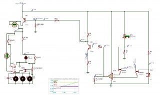
It has been a very long time since I’ve done any real circuit design. At work I frequently review schematics to understand how things work, but leave the fine details and analysis to our electronic design team. So the first step was to simulate the circuit using Proteus. I had not used this software before, but it seemed somewhat intuitive to use. I think there are many issues with the simulation of the active parts, but I was able to work around these issues to get things going. I also think that their could be a lot of work on the usability of the program to make it more natural to use.
Temperature Fan Circuit
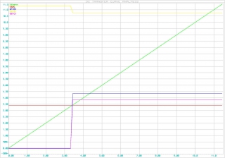
This is a graph of the simulation. What it shows is right at the Vset voltage (the voltage that I want to turn the fan on) the comparator goes from low to high and then the Q2(C) goes from 0V to about 3.6V. In reality after testing this circuit the voltage at Q2(C) is the about 12V. I couldn’t figure out why Proteus was modeling this wrong, but it works so I’m happy.
Power Supply Circuit
Once I had the main circuit working I started to add the power supply into the design. My simple power supply is to give me a 12V ~1A drive. I had bought all the part to support up to 1.5A, but after seeing the size of the transformers I settled on a 1A transformer. In both the sim and on the bread board I was seeing my 12V supply voltage drop way down. I wrote a quick post about it which is really a link to the Electronics Point forum. So that this blog post is complete I’ve cut, pasted, and modified select posts from the forum below.
Problem Statement:
I have a L7812 setup to give my circuit a 12V DC power. The L7812 has bridge rectifier, caps, and transformer 120V to 15V. From the LM7812 I pass the current through a pnp transistor that is fully saturated. Looks like I get about 18-19V into the L7812 and when the motors (small pc fan motors) are off (pnp open) I see a stable ~12V.
I have a small resistor in series (out of motors to ground) with the motors (3 in parallel) to limit the current. The motors are expected to draw 100mA. So I expect to drop a bit over 300mA across the circuit. My transformer and L7812 are all spec for up to 1A. When I turn the motors on (pnp saturated) the voltage sags to near 9V pulling about 300mA. So I’m not too sure why I’m seeing the sag as I should be able to drive plenty of current and with my resistor in series of the current path there should be current limited.
Any ideas? Thank you.
Issues:
(Harald Kapp) C2 is far too small. A rule of thumb is 1000µF per 1A of current, so instead of 33µF you should have at least 330µF at 300mA. I suggest 1000µF. If you measure the input voltage of the 7812 with an oscilloscope you will see lots of ripple with your current setup.
Resolution
Just added the 1000uF on the input and the voltage sag is gone.
With the power problem fixed my circuit worked! Now it was time to transfer my prototype to a PCB board. Soldering everything together went rather smoothly. The hardest part was holding the circuit and soldering at the same time. For all of my college projects we pretty much always did this work in a two person team which made things much easier and faster. As for packaging, I used an old wasabi peanut container, spray painted it black, and made cuts where I needed them. Not too fancy but it looks okay when sitting in the entertainment center. The fans used are basic PC fans. My circuit is designed to support 1A so I needed to be somewhat careful of which fans I bought. Tom helped me
After all the help here is the final (really simple) circuit.
Prototyping
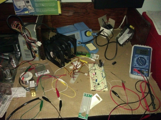
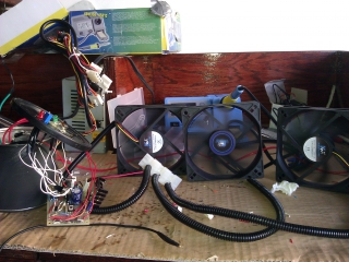
As I mentioned the active parts didn’t simulate too well. So once I got something working close to what I wanted I placed the circuit on a bread board to see if it was functional. After some testing I then went back to the simulation and repeated this cycle several times. In my prototyping stages I used an old pc power supply for the 12V into my circuit. This worked out pretty well other than it ended up being another mini-project just to get the power supply working again.
Here is a quick picture of my test bench.
Assembly & Test
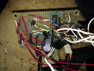
After the prototype checked out against the simulations (or verified where the sim was incorrect) it was time to wire it all up. I remember now why in college we always worked in twos when soldering; it is really hard to solder by yourself, holding the solder, the board, and the soldering iron is tough with two hands and without a good holder.
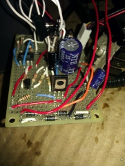
As I placed parts I periodically did checks to make sure I didn’t short anything out unexpectedly. Also, I planned for the external inputs to be along the edges which worked out pretty well, but I neglected to set up the power rails in a very good place which in my opinion makes the circuit look a bit ugly. (Yes, I’m an engineer and circuits can be pretty and ugly).
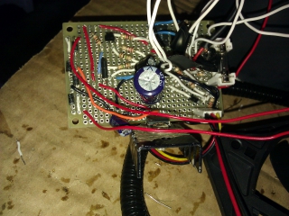
A few angles of the board
angle #2
angle #3
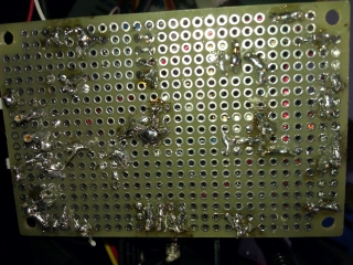
The bottom of the board
Once it was all put together I made a several measurements of how the circuit was working, but I seem to have lost them. Well, at any rate, the circuit was working as I expected.
Final Integration
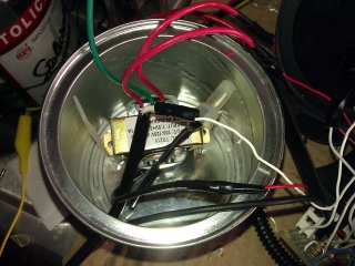
Here are the final integration pictures, right before things are all buttoned up
Looking inside the canister with the AC-AC converter. I ended up zip tying it down to the bottom which worked out really well. (which is kind of funny if you know about our latest Jeep incident where the techs broke something and used a zip tie to fix it).
Everything plugged in and working before I close up the lid
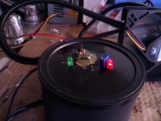
Top of the Lid
Final Product
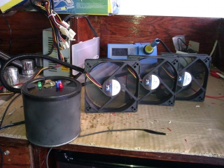
There are two final product images. The first is from the garage.
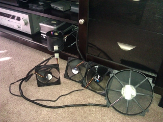
I did some testing inside my entertainment center and decided I needed more powerful fans to move the air. So this second image is in from of the entertainment center with more powerful fans attached.
Final Thoughts
As a last second addition I placed a green LED to indicate if it was on or off. With all the fans in place it seems to work pretty well except for when the playstation is going. The PS3 just generates too much heat for me get out through just the back. So for now when I use the PS3 I still open up the doors. All in all, this worked out pretty well and is step 1 in baby proofing the entertainment center. Step 2 will be to lock the sliding doors and drawer, but that is a project for another day.
I’m happy I was able to make a circuit after not doing anything like this in a really long time and I had fun doing it. Perhaps I slightly earned my EE license for the year. It took way way longer than I expected which Lisa didn’t care for my late nights much. I think the cost of this thing was about $40, but I bought a lot of spare parts for future projects and really don’t know what the exact cost was.
Here is a zip file of the PDF and design files if anyone is looking for them
Temperature-Controlled-Fan-Final-Design.zip

